 Most viewed - Constructing Wireless Sites
|

15 - Vandals Strike!1410 viewsOkay, I'll start by saying it wasn't me! Really!! Someone(s) climbed our little friend and installed some cute "eyes" at the top of the pole. The eyes remained in place for about two weeks near Christmas time 2002.
|
|

Chris Hicks, Chief Engineer1401 viewsChris Hicks is the Amaturo Group's RF engineer responsible for getting the new KMLT from dirt to on-the-air. He's (proudly) standing by the KMLT transmitter, which is temporarily installed in a trailer while the permanent underground transmitter building is being constructed nearby.
|
|

08 - Faux Branches Installed1362 viewsOur little tree is taking shape now the branches have been installed. Notice the unprotected coaxial cables running to the tree near the base (right side).
|
|

17 - Side view of Our Little Friend1360 viewsJanuary 2, 2005 was a cold, damp day in Southern California, but I managed to snap a photo of our little tree to better show the new antennas mounted off of the trunk, and the new sickly green quad antennas. Also notice a small "Keep Out" sign at the lower left corner of the front fence. I'm sure that it is very effective.
|
|

18 - Our little friend has changed and grown!1323 viewsThis photo, taken in November, 2004 shows (1) that the second-to-the-right antenna has been changed out without much regard to color matching, (2) that a new dual-band antenna has been added on trunk below the prior-existing antennas, and (3) that the faux branches have been extended down the trunk to provide partial cover for the new antenna.
Note that the replacement dual-band antenna has its four cable ports visible on the bottom of the antenna, unlike the existing with hidden rear connectors. Most unsightly!
Sad, sad little tree.
|
|

Looking at the antenna of an FM broadcast station1296 viewsThis is the omni-directional cross-polarization antenna used at KMLT-FM in Thousand Oaks, California. It's a one-of-a-kind antenna design by SPX Corporation's Dielectric division.
|
|

RF Safety testing at an FM broadcast station1250 viewsThis is a photograph of RF engineer Joel Saxberg conducting signal strength measurements to determine the boundary to the general population/uncontrolled area around the antenna. Due to signal strength of the station, a fence will be placed around the antenna site to keep out the public out of the RF controlled zone.
|
|

14 - Mother Earth Starting to Reclaim...1234 viewsNature (with the help of plantings by the carrier) is starting to retake the base of the site.
|
|

09 - Construction of the Ice Guard1053 viewsA box to protect the coaxial cables (often called an ice guard) is installed at the base of the of the trunk. The cones are cute, eh?
|
|

The Business End of KMLT1049 viewsThis is a closeup of KMLT's transmitter antenna. A simple, elegant design. May, 2006.
|
|

16 - Equipment Shelter and Pad for Our Little Friend1042 viewsThis is the first good shot I've been able to take of the equipment building for our little friend. It's a long shot, taken with a telephoto lens, but you can clearly see the equipment building for the original carrier, and the pad-mounted equipment for the new carrier (on the trunk). Photograph 04 in this gallery shows the relative positions of the equipment building and our little tree.
|
|

10 - Close up of Ice Guard Construction1002 viewsThe title of this slide says it all.
|
|

Connecting the coax and ground strap to the antenna and post1002 viewsThe transmitter coaxial cable (black) connects to the rigid coaxial rider inside the antenna support to feed the antenna. The very wide copper strap provides an unbroken ground connection between the antenna and the underground transmitter building about 700 feet away.
|
|

Looking at the antenna of an FM broadcast station938 viewsHere's a photograph of KMLT-FM's antenna and supporting post from a vantage point near the location.
|
|

RF Safety testing at an FM broadcast station (#2)925 viewsTesting the level of RF emissions to determine compliance with FCC OET 65. The engineer in the picture is Joel Saxberg of Beem Co., a contractor of KMLT-FM in Thousand Oaks, California
|
|
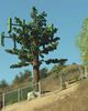
13 - Basically Complete923 viewsThis is a photo of the site at completion.
|
|

Rebar cage for underground transmitter building918 viewsHere's a good show showing how much rebar has been placed in the past 7 days (see the other photo in this gallery). The temporary transmitter trailer is shown in the background. Chris Hicks, the RF engineer responsible for making this site operational, is in the white shorts behind/above the excavation.
|
|

KMLT Antenna and Support918 viewsThe steel pole supporting the antenna is now painted blue to help it blend into the sky background.
|
|

34. A Loose Wire?918 viewsThe loose wire is actually a ground wire. The rolling portion fo the fense is grounded via this lead.
|
|

Panoramic view of the KMLT work site and antenna905 viewsThe trailer with the cable reel on top is the temporary transmitter location; the permanent underground transmitter building is behind the below the portable chain link fence behind the Bobcat. Zoom in on the ridge line to just make out the antenna location.
|
|

12 - Fence Installation and Ice Guard Completion903 viewsA very short (and hardly functional) fence is installed, and the ice guard is covered.
|
|

11 - Ice Guard Construction Nearly Complete899 viewsThe frame for the ice guard is basically complete. Soon it will be covered.
|
|

Inside the Transmitter Vault871 viewsLooking northwest, this photo shows the air conditioning ports and the entry door.
|
|

Painting on the Sky 1 of 6867 viewsAs a condition of its City of Thousand Oaks construction permit, KMLT is required to paint the antenna pole sky blue. This photo shows the crane and bucket used as the painting platform. May, 2005.
Photo thanks to Bill Cloutier.
|
|

KMLT On-the-Air and Out-of-Sight865 viewsCompare this photograph of the 'finished product' with photos I took during construction. Chris Hicks, the City of Thousand Oaks, and COSCA worked together to create an invisible transmitter shelter in 'open space.' May, 2006.
|
|

07 - Antennas Installed, Connected860 viewsThe techs have installed the panel antennas on the arms, and are now connecting the coaxial cables to the antennas.
|
|

04 - Cables Pulled in Trunk860 viewsThe coaxial cables that will be connected to the antenna are pulled from the BTS equipment to the top of the trunk. Photograph 16 in this gallery is an excellent, if long shot, of the equipment building seen here, above and behind our little tree.
|
|

Hey, it's a good thing they got the weatherproofing on the building!858 viewsIt's been raining 'round our soon-to-be underground friend. Notice that the conduits are extended through the precast holes.
|
|

03 - Trunk Installed855 viewsThe "trunk" of the cell pine is installed on the concrete base. Note the pegs used to receive the branches, and the cable portal at the top of the trunk.
|
|

Painting on the Sky 6 of 6831 viewsThe pole is now painted. May, 2005.
Photo thanks to Bill Cloutier.
|
|

Painting on the Sky 2 of 6815 viewsBill's in the bucket applying primer, then paint, to the PCV pole supporting KMLT's antenna.
Photo thanks to Bill Cloutier.
|
|

Verizon CEV installation in Irvine, California815 viewsWorkers preping the CEV for the concrete pour.
|
|

Verizon CEV installation in Irvine, California812 views
|
|

05 - Antenna Bracket Assembly810 viewsA technician is constructing one of the two antenna support arms.
|
|

View inside the Transmitter Vault810 viewsHere's a view facing southwest inside the equipment vault. The large openings are for air conditioning. The cable conduit entry ports can be seen in the upper-far corner of the same wall. Photo by Bill Cloutier.
|
|

06 - Antenna Arms Installed809 viewsThe antenna support arms are installed. The coaxial cables are fanned out to the arms to match to the antennas that will be installed later.
|
|

02 - Concrete Base Installed808 viewsThis photo simulation shows the base installed before the installation of the "trunk" of the cell pine.
|
|

KMLT Transmitter Vault Hatch...almost807 viewsThe site will awaits a metal hatch for the transmitter vault to complete the site security.
|
|

28. Close up of the Site Name Sign804 viewsIt's for sure...We'll call this Armacost!
|
|
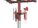
So, it works in orange, too!803 viewsThis is a Clearwire site near the Portland, Oregon airport (PDX). Sites near airports are sometimes required to be painted with aviation orange and while to make them more visible to pilots. Clearly seen in this photo are Clearwire's on panel-per-sector deployment for serving the customers in the area, and two backhaul microwave antennas to link this site to other site, and on to the Clearwire POP ("point of presence") connecting to the Internet.
|
|

01 - Before769 viewsThis is a photo simulation of the site prior to the installation of the concrete base. (SORT by "TITLE +" or "TITLE -" in the upper right of the thumbnail frame to see these photos in the proper order!)
|
|

Cabinet Pads in the Transmitter Vault751 viewsThe raised concrete pads lift the transmitter and air conditioning cabinets off of the floor. That's real handy where water might pool around it, don't ya know! Photo by Bill Cloutier.
|
|

Light Standard Under Construction749 viewsThe double arms of this light standard, and the radome containing the antennas above the arms are yet to be placed. The light standard is located in the greenbelt median of the roadway.
|
|

KMLT's Antenna and Support Pole747 viewsThis photograph captures the final execution of KMLT's antenna. Yes, the steel support pole is painted sky blue. May 2006.
|
|

Painting on the Sky 3 of 6740 viewsBill continues his way down the the PCV pole supporting KMLT's antenna.
Photo thanks to Bill Cloutier.
|
|

KMLT Antenna and Support737 viewsThe steel pole supporting the antenna is now painted blue to help it blend into the sky background.
|
|

KMLT Almost Buried721 viewsIf you compare this photo with past photos you'll notice that half the transmitter building is now buried. When complete only the ground level access in the foreground of the building will remain. The pullbox to the left of center is for electrical power. The pullbox to the far right is for the coaxial egress point to feed the antenna.
|
|
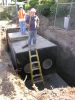
Not part of an underground water river...716 viewsThe water bottle is not part of the CEV.
|
|

Constructing the underground transmitter building for KMLT-FM709 viewsThis photograph shows the excavation and initial construction for the underground transmitter building to house KMLT-FM in Thousand Oaks, California. If you look carefully at the middle of the ridgeline you can just see the antenna and antenna post about 700 feet away.
|
|

KMLT Almost Buried - Just a few weeks of work left!709 viewsThe underground transmitter building is almost complete. Just waiting on the stairs and hatch to be installed. The fencing is still not in final shape at the antenna. Most of the construction 'stuff' has left the site for points unknown. April 2005.
|
|

Painting on the Sky 6 of 6707 viewsA close up of Bill priming the next section of the pole, and...from the looks of it...part of his left hand.
|
|

View of the transmitter site from near the antenna site703 viewsHere's an updated view of the KMLT transmitter area take from about 600 fee up the hill (very near the antenna site).
|
|

700 views
|
|

Waterproofing the KMLT transmitter building689 viewsThe external concrete forms and braces have been removed; the outside is treated for waterproofing; and the pre-cast holes to permit conduit/cable entry are now visible.
|
|

Looking at the entry area.688 viewsHere's a good look at the entry area and the conduits extending from the transmitter building to what will be underground when the earth is pushed back around the building.
|
|

Panoramic view of KMLT - 90% backfilled683 viewsThe entire 'back' portion of the transmitter building is now under dirt. Due to the new location of the trash bin, this panoramic photo is taken from a point to the north of the previous panoramic shots.
|
|

Waterproofing the KMLT transmitter building682 viewsAnother view of the transmitter building and the waterproofing.
|
|

The Transit Mixer has Arrived...681 views...so let the pouring begin!
|
|

Rebar cage for underground transmitter building - From ramp678 viewsAnother shot of the rebar that forms the soon-to-be underground transmitter building. The roadway in the background goes to the antenna site, adjacent to a camouflaged water tank.
|
|

Light Standard Under Construction676 viewsThe double arms of this light standard, and the radome containing the antennas above the arms are yet to be placed.
|
|

2. Routing the Antenna Cables up to the Roof675 viewsThe coaxial cables for the antennas, including the GPS antenna, are loosely placed against teh wall going up to the roof. As you'll see later, these cables will be secured in a cable tray. At this time the GPS antenna is not yet installed.
|
|

KMLT Panorama - Almost Done673 viewsThe site is nearly complete. Transmitter vault awaits a final hatch assembly.
|
|

1. Antennas to be Hidden in Clock Tower673 viewsThree of four sides of the exsting clock tower had walls partially removed to permit the installation of RF-transparent fiberglass panels. As you'll see later, once the antennas are installed behind the panels, the panels are painted and textured to match the rest of the structure, thus hiding the antenna locations.
|
|

KMLT Panorama - Almost Done672 viewsThe site is nearly complete. Transmitter vault awaits a final hatch assembly.
|
|

Don't worry...the ladder will be removed before the concrete is poured.671 viewsWorkers preping the CEV for the concrete pour. The large holes are to connect to what will be intake and outflow air vents yet to be installed.
|
|

Panoramic view of the KMLT work site and antenna (Waterproofing)670 viewsThis panoramic view shows the worksite, the antenna and tower, and the transmitter building with the waterproofing applied to the walls.
|
|

Painting on the Sky 5 of 6669 viewsBill's painting on the sky!
|
|

Gimme a Transmitter with Mustard!669 viewsAnother view of the at-grade grill over the transmitter room at KMLT. May 2006
|
|

32. Looking down on the Activated Site665 viewsHere's the bird's-eye view looking down at the BTS equipment mounted on the far pad.
|
|

14. Installing the Telco Interface and Power Switching Cabinets664 viewsThe large cabinet on the right (with the open door) is to house the telco interface. A telco dataline is used to connect this cell site back to Verizon's mobile telephone switching office. The two smaller cabinets on the left, starting at the far left, are the power breaker panel, and the power generator transfer switch. The transfer switch senses loss of commercial power and automatically starts the generator (yet to be installed) and transfers power to the generator once stabilized. The reverse occurs when the commercial power is restored for a minimum period of time.
|
|

Panoramic view of the KMLT work site and antenna (Roof on)662 viewsThis is an updated panoramic shot of the job site and antenna. The roof is now on the building. Photo taken on a weekend (no workers present).
|
|

KMLT's Antenna Fence Under Construction660 viewsAnother view of the antenna, and the fence being constructed is to keep the hikers away from the antenna site.
|
|

KMLT's Antenna Fence Under Construction658 viewsThe fence being constructed is to keep the hikers in the area away from the antenna site. At the time this photo was snapped KMLT was operating from its old (aux) transmitter site some miles away.
|
|

29. Which Way Tray?655 viewsIt's now January, 2006. The site is active (but without a backup power generator). It seems that the installers missed putting all of the covers on the cable tray. Too bad.
|
|

Panoramic view of KMLT - 75% backfilled651 viewsThis panoramic photo of the site shows the building backfill nearly complete. Soon it will be time to move in the transmitter and related equipment.
|
|

About 75 percent of the building is buried649 viewsThe backfill is covering the building up to about the 75% level. Soon it will be completely buried, and the transmitter and related equipment will be moved in.
|
|

Panoramic view of the KMLT work site and antenna (Zoom shot)642 viewsThis close-up panoramic shot shows the transmitter site as seen (well, actually, not seen) from near the antenna site.
|
|

The walls are up...640 viewsThe concrete calls are poured and are hardening. Next, in about 6 days, comes the roof pour and cure.
|
|

Where's the Transmitter?639 viewsLooking down from near the antenna, the underground FM transmitter housing is nowhere to be seen! May 2006.
|
|

Cable route in/out of the CEV638 viewsThis trench will house the power and telephone cable conduits into and out of the CEV, as well as the coaxial cables to the base of the light standard.
|
|

Now the walls are up...632 views...another view with the side walls poured. The roof is yet to come.
|
|

A Well-Done Grilled FM Station632 viewsKMLT's transmitter housing present appearance as of May, 2006 is virtually invisible. Easy to miss. Exactly what was intended! Outstanding work by Chris Hicks, KMLT's CE, the City of Thousand Oaks Planning department, and the Conejo Open Space Conservation Agency
|
|

Looking at the rear of the CEV.631 viewsA good shot of the base and read of the CEV dig hole.
|
|

KMLT's Roof is On629 viewsIn three weeks the roof will cure and dirt will be pushed to close in the hole.
|
|

27. The Name Goes On Before the Quality Goes In629 viewsThe pad has been poured, again, and the fense is on it's tracks. No BTS yet, but the site sign has gone up announcing to the world that this is Verizon's Armacost site!
|
|
628 views
|
|

31. Cable Termination to BTS Jumpers627 viewsHere's a nice photo of the the cable terminations for the hardline cable to/from the roof, and the jumper to the equipment cabinet. The colored bands identify what cable is connected to what antenna.
|
|

33. Personals Ad: "Concrete Pad Sks Standby Pwr Gen!"623 viewsAs noted above, the standby power generator isn't (yet) installed here. Who knows...maybe it'll never be installed, but if it is, this is where it'll go.
|
|

622 views
|
|

3. Base Telecommunications Station Equipment618 viewsThis new addition to the existing structure at the rear of the building is to house the BTS equipment, plus a future standby power generator, power switching equipment, and a telephone interface panel. The standby power generator pad is the the one nearest the fence. The BTS equpipment pad is to the rear-left in this photo. Later, things will change a bit...oops!
|
|

CEV ready for concrete pour618 viewsJust waiting on the transit mixer to show up.
|
|

Panoramic view near antenna looking at the KMLT work site616 viewsHere's a good overview of the KMLT transmitter site, under construction, and the City of Thousand Oaks in the background. The camera position is about 30 feet south of the antenna.
|
|

30. BTS Installed and Humming615 viewsThe site is active. This photo is looking down on the site BTS equipment cabinet through the roof fence. You'll see more of the fense in a later photo.
|
|
610 views
|
|

8. Installation of the Cable Tray to the Roof606 viewsThe techs are installing the cable tray. Once installed, the coaxial cables will be lashed to the ladder arms to provide for support, and to prevent excessive bending of the coaxial cables.
|
|
605 views
|
|
604 views
|
|
601 views
|
|
597 views
|
|

16. Clock Tower Painting Underway595 viewsYet another view of the re-painted clock tower.
|
|

4. BTS Pad and Cable Termination593 viewsThe raised concrete pad is to support the BTS equipment. The cables that dead-end in the wall-mounted tray will connect the roof antennas to the BTS.
|
|

12. Close-up of GPS antenna and top of Cable Tray593 viewsAs noted before, the cables are carefully pulled on to the roof so as to prevent kinks. The GPS antenna provides system synchronization time signals. This location is inferior as it can been seen from the ground. A better location would have been on the roof away from the edge so as to hide this element.
|
|

25. It's Raining, It's Pouring (Concrete)592 viewsHere's the new re-poured pad. It's just been poured. There'll be a cure period to let it harden before moving the equipment into the area.
|
|

10. Securing the Coaxial Cables in the Tray591 viewsA tech secures the cables to the tray. Notice that the cable tray extends out a bit from the edge of the wall. This will connect with the vertical portion of the tray heading to the roof.
|
|

9. More Cable Tray Installation591 viewsHere's a further view of the cable tray as it transitions from the hallway leading from the side of the building over and down to the BTS equpment housing area.
|
|

Panoramic view of KMLT after a rain...589 views...well, really, a significant Southern California storm on December 29, 2004.
|
|

15. Clock Tower Painting Underway585 viewsThe panels are fully installed and are being painted and textured to match the building.
|
|

6. A Close-Up View of Two Sectors of RF-Transparent Panels584 viewsYet another view of the bell tower being modified to enclose the antennas.
|
|

11. Cables are now in the Cable Tray582 viewsWe're getting closer! Notice that the cables make a gentle (less than 90 degree) bend at the bottom of the ladder where it connects to the tray in the hallway. Bending cables too much can kink them. Kinking can cause excessive signal transmission losses. Not a good thing! Also notice that the GPS antenna is now installed--quite visibly--at the top of the cable tray on the roof. More in the next photograph...
|
|
582 views
|
|

578 views
|
|

17. Clock Tower Painting Underway577 viewsA rear view of the re-painted clock tower.
|
|

Nearly time for the 'crete!572 viewsWorkers preparing the CEV for the concrete pour.
|
|

26. Anyone for a Tumble?571 viewsThe concrete mixer has done its job and is ready to go home, again!
|
|

21. Huh? What Happended to the Concrete Pad?567 viewsIn a surprising twist, the concrete pad has been hammered out and new frames and conduits installed. What gives? According to the work crews, it seems that the generator pad was installed 90 degrees off. Go back in the gallery and look and you'll see what I'm talking about. Because of the little error, weeks were apparently lost in site activation...not to mention $$$ (which I didn't, okay?).
|
|
567 views
|
|

20. The Scaffolding is Down565 viewsHere's a good shot of the clock tower with the scaffolding removed. Nice pic at sunset, eh?
|
|

18. Now You See the Cables...Now You Don't564 viewsThe cables are now safely tucked away under the cover of the tray, now installed.
|
|
564 views
|
|
563 views
|
|

13. Securing the Cables and Painting557 viewsThings are moving forward downstairs, too!
|
|

5. A Close-Up View of Two Sectors of RF-Transparent Panels554 viewsHere's a close-up of the bell tower being modified to enclose the antennas. The cut-outs on the front and left side of the tower are the RF transparent panels.
|
|

Panoramic view of the KMLT transmitter building553 viewsThe roof is on. Less than a month to go before the hole is closed and the building is buried.
|
|

24. It's Concrete Pour Day...Again546 viewsThe wood frames are in place and braced for the pour...again. Notice the very nice cable terminations at the far end of the cable tray. You'll see these again, later.
|
|

7. A Close-Up View of Two Sectors of RF-Transparent Panels543 viewsThis is a close-up of the rear of the bell tower modified to enclose the antennas.
|
|

19. Now You See the Cables...Now You Don't536 viewsAnd the cables in the BTS area are also safely tucked away under the cover of the tray.
|
|

23. An outside view fo the BTS Equipment Area528 views...with the sliding fense not installed on the track, yet.
|
|

22. Another View of the New Generator Wood Frame510 viewsYup, it's clearly rotated 90 degrees from before. Oh well.
|
|
|
|
|


 Home
Home Login
Login Reprint Permissions
 Album list
 Last uploads
 Last comments
 Top rated
 My Favorites
 Search