 Most viewed - Verizon's "Armacost" Site in West Los Angeles
|
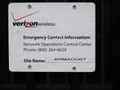
28. Close up of the Site Name Sign640 viewsIt's for sure...We'll call this Armacost!
|
|
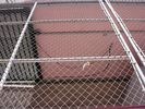
34. A Loose Wire?544 viewsThe loose wire is actually a ground wire. The rolling portion fo the fense is grounded via this lead.
|
|
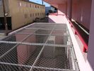
32. Looking down on the Activated Site501 viewsHere's the bird's-eye view looking down at the BTS equipment mounted on the far pad.
|
|

2. Routing the Antenna Cables up to the Roof498 viewsThe coaxial cables for the antennas, including the GPS antenna, are loosely placed against teh wall going up to the roof. As you'll see later, these cables will be secured in a cable tray. At this time the GPS antenna is not yet installed.
|
|
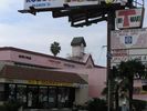
1. Antennas to be Hidden in Clock Tower490 viewsThree of four sides of the exsting clock tower had walls partially removed to permit the installation of RF-transparent fiberglass panels. As you'll see later, once the antennas are installed behind the panels, the panels are painted and textured to match the rest of the structure, thus hiding the antenna locations.
|
|
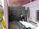
14. Installing the Telco Interface and Power Switching Cabinets488 viewsThe large cabinet on the right (with the open door) is to house the telco interface. A telco dataline is used to connect this cell site back to Verizon's mobile telephone switching office. The two smaller cabinets on the left, starting at the far left, are the power breaker panel, and the power generator transfer switch. The transfer switch senses loss of commercial power and automatically starts the generator (yet to be installed) and transfers power to the generator once stabilized. The reverse occurs when the commercial power is restored for a minimum period of time.
|
|
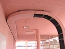
29. Which Way Tray?465 viewsIt's now January, 2006. The site is active (but without a backup power generator). It seems that the installers missed putting all of the covers on the cable tray. Too bad.
|
|
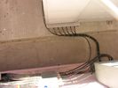
31. Cable Termination to BTS Jumpers454 viewsHere's a nice photo of the the cable terminations for the hardline cable to/from the roof, and the jumper to the equipment cabinet. The colored bands identify what cable is connected to what antenna.
|
|
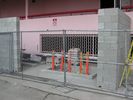
3. Base Telecommunications Station Equipment442 viewsThis new addition to the existing structure at the rear of the building is to house the BTS equipment, plus a future standby power generator, power switching equipment, and a telephone interface panel. The standby power generator pad is the the one nearest the fence. The BTS equpipment pad is to the rear-left in this photo. Later, things will change a bit...oops!
|
|
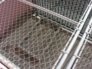
33. Personals Ad: "Concrete Pad Sks Standby Pwr Gen!"439 viewsAs noted above, the standby power generator isn't (yet) installed here. Who knows...maybe it'll never be installed, but if it is, this is where it'll go.
|
|
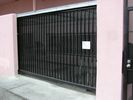
27. The Name Goes On Before the Quality Goes In433 viewsThe pad has been poured, again, and the fense is on it's tracks. No BTS yet, but the site sign has gone up announcing to the world that this is Verizon's Armacost site!
|
|
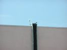
12. Close-up of GPS antenna and top of Cable Tray431 viewsAs noted before, the cables are carefully pulled on to the roof so as to prevent kinks. The GPS antenna provides system synchronization time signals. This location is inferior as it can been seen from the ground. A better location would have been on the roof away from the edge so as to hide this element.
|
|
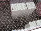
30. BTS Installed and Humming423 viewsThe site is active. This photo is looking down on the site BTS equipment cabinet through the roof fence. You'll see more of the fense in a later photo.
|
|
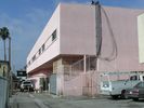
8. Installation of the Cable Tray to the Roof418 viewsThe techs are installing the cable tray. Once installed, the coaxial cables will be lashed to the ladder arms to provide for support, and to prevent excessive bending of the coaxial cables.
|
|
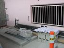
4. BTS Pad and Cable Termination413 viewsThe raised concrete pad is to support the BTS equipment. The cables that dead-end in the wall-mounted tray will connect the roof antennas to the BTS.
|
|
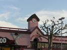
20. The Scaffolding is Down413 viewsHere's a good shot of the clock tower with the scaffolding removed. Nice pic at sunset, eh?
|
|
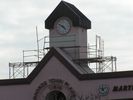
6. A Close-Up View of Two Sectors of RF-Transparent Panels405 viewsYet another view of the bell tower being modified to enclose the antennas.
|
|
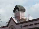
16. Clock Tower Painting Underway404 viewsYet another view of the re-painted clock tower.
|
|
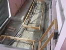
21. Huh? What Happended to the Concrete Pad?404 viewsIn a surprising twist, the concrete pad has been hammered out and new frames and conduits installed. What gives? According to the work crews, it seems that the generator pad was installed 90 degrees off. Go back in the gallery and look and you'll see what I'm talking about. Because of the little error, weeks were apparently lost in site activation...not to mention $$$ (which I didn't, okay?).
|
|

11. Cables are now in the Cable Tray396 viewsWe're getting closer! Notice that the cables make a gentle (less than 90 degree) bend at the bottom of the ladder where it connects to the tray in the hallway. Bending cables too much can kink them. Kinking can cause excessive signal transmission losses. Not a good thing! Also notice that the GPS antenna is now installed--quite visibly--at the top of the cable tray on the roof. More in the next photograph...
|
|
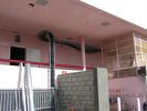
9. More Cable Tray Installation395 viewsHere's a further view of the cable tray as it transitions from the hallway leading from the side of the building over and down to the BTS equpment housing area.
|
|
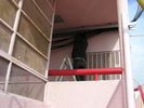
10. Securing the Coaxial Cables in the Tray394 viewsA tech secures the cables to the tray. Notice that the cable tray extends out a bit from the edge of the wall. This will connect with the vertical portion of the tray heading to the roof.
|
|
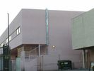
18. Now You See the Cables...Now You Don't388 viewsThe cables are now safely tucked away under the cover of the tray, now installed.
|
|
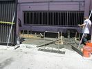
25. It's Raining, It's Pouring (Concrete)386 viewsHere's the new re-poured pad. It's just been poured. There'll be a cure period to let it harden before moving the equipment into the area.
|
|
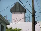
17. Clock Tower Painting Underway385 viewsA rear view of the re-painted clock tower.
|
|
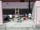
13. Securing the Cables and Painting378 viewsThings are moving forward downstairs, too!
|
|
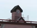
15. Clock Tower Painting Underway378 viewsThe panels are fully installed and are being painted and textured to match the building.
|
|
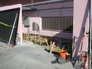
24. It's Concrete Pour Day...Again377 viewsThe wood frames are in place and braced for the pour...again. Notice the very nice cable terminations at the far end of the cable tray. You'll see these again, later.
|
|
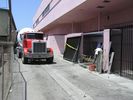
26. Anyone for a Tumble?376 viewsThe concrete mixer has done its job and is ready to go home, again!
|
|

5. A Close-Up View of Two Sectors of RF-Transparent Panels372 viewsHere's a close-up of the bell tower being modified to enclose the antennas. The cut-outs on the front and left side of the tower are the RF transparent panels.
|
|
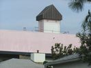
7. A Close-Up View of Two Sectors of RF-Transparent Panels370 viewsThis is a close-up of the rear of the bell tower modified to enclose the antennas.
|
|
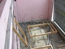
22. Another View of the New Generator Wood Frame370 viewsYup, it's clearly rotated 90 degrees from before. Oh well.
|
|
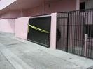
23. An outside view fo the BTS Equipment Area370 views...with the sliding fense not installed on the track, yet.
|
|
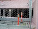
19. Now You See the Cables...Now You Don't367 viewsAnd the cables in the BTS area are also safely tucked away under the cover of the tray.
|
|
|
|
|
|
